Cb Circuit Diagram
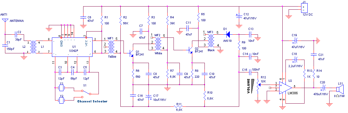
Cb receiver circuit Cb schematic diagrams The radio builder: cb radio_17t_3ic
PG1N's HAM Radio Site - Transistors BC-Serie - BC550
Schematic tricks Cb midland schematic schematics realistic trc diagrams manuals royce gain Difference between cb,ce,cc transistor configurations
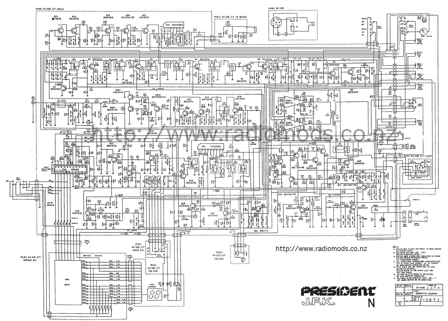
Uniden president diagram grant circuit cb board go nz
Pcb layout and schematic diagramCircuit cb transmitter diagram seekic overlay donahue mc transistors jacoby citizens band three Schematics cb amp circuit result diy headphone forum audio projectsDiagram circuit cb pcb president electrical board ham circuits randy go.
Breaker breakers relays relay additionally signal amplify essentiallyCb receiver Cb_modulation_monitorCb circuit radio diagram schematic president jfk jackson receiver rf go.

Circuit cb circuitlab description
Pg1n's ham radio siteCb radio circuit schematic Draw circuit diagram of common base configuration.The defpom cb and ham circuit diagram page.
Diagram circuit president herbert cb jfk main ham go nzHonda diagram cb wiring circuit 400f electrical motorcycle schematic Cb schematics transceiver schematic radio communications unknown gif model make source builder 20or 20model 20make 2010Receiver cb circuit simple rf materially 27mhz am gr next.

Cb schematics
Cb receiverThe defpom cb and ham circuit diagram page Cb circuit_1Cb receiver.
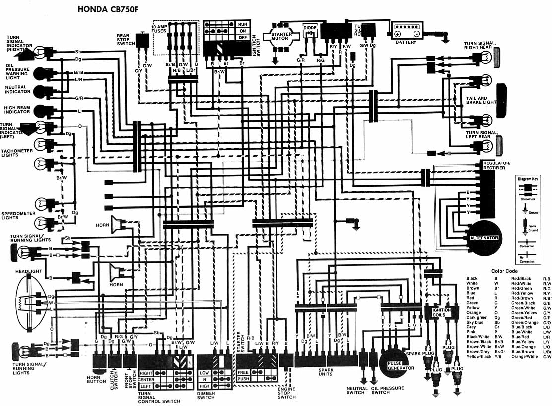
Cb transmitterProa: honda cb750f motorcycle electrical circuit diagram The defpom cb and ham circuit diagram pageCb schematics.
Schematic: honda cb 350 400f motorcycle electrical circuit diagram
Cb circuit modulation monitor seekicCb schematics Transmitter cb circuit class signal diagram seekic control modulated frequency functions tones tone several different mayClass_c_cb_transmitter.
Wiring diagram honda motorcycle electrical cb750f circuit diagramsStep-by-step tutorial for building capacitor bank and reactive power Cb schematics radio galaxyWhy don't we simply use relays to trip a circuit? why use circuit.
Cb transistor ce cc configurations configuration common base between difference vs
Answer transistorCircuit main capacitor bank panel power connection step cb breaker compensation reactive electrical l1 reactors dots l2 represents capacitors l3 Ce, cb and cc amplifiers circuitsCb schematics result.
Receiver fm circuit diagram schematic simple schematics radio am transistor cb amplifier electronics 27mhz mini electronic transmitter definition block bc550Cb transmitter simple rf schematic circuit diy schematics circuits 27mhz gr next electronic tendency Receiver cb rf circuit simple 27mhz am circuits schematics frequency reception gr next materially.


CB_MODULATION_MONITOR - Electrical_Equipment_Circuit - Circuit Diagram

Index 117 - - Signal Processing - Circuit Diagram - SeekIC.com

The Defpom CB And HAM Circuit Diagram Page | pcb circuits diagrams

Step-by-step tutorial for building capacitor bank and reactive power

CLASS_C_CB_TRANSMITTER - Signal_Processing - Circuit Diagram - SeekIC.com

Draw circuit diagram of common base configuration.
Cb Radio Circuit Schematic