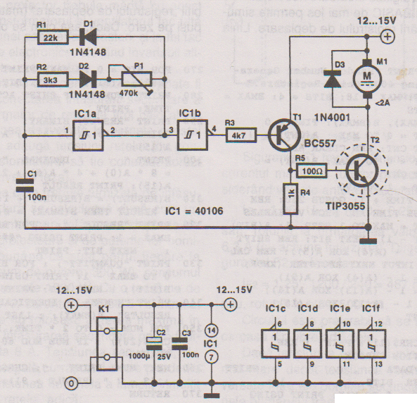
Circuit Diagram Of Pwm
How to generate pwm using ic 555 Pwm lm324 220v circuito amplificadores operacionales circuitos ventilador mosfet Arduino pwm modulation analog potentiometer connected digital
Universal PWM Driver Schematic Circuit Diagram
3: a practical pwm circuit. Motor circuit dc pwm control 90v building speed schematic electrical 20amps work will resistors ballast electronics stack Circuit schematics
Pwm microcontroller generating mplab xc8 registers ccp
How to design the pwm circuitryUsing the sg3525 pwm controller Pwm circuit signal diagram seekic processing transistor generatorPwm modulation pulse width circuit tutorial control generator circuits frequency groovy using power diagrams make making.
Generating pwm with pic microcontroller using hi-tech cResults page 2, about 'pwm'. searching circuits at next.gr Hho: pwm circuit diagram for hhoShows the complete circuit diagram of the pwm inverter circuit. ic 3.

Circuit for implementing the pwm scheme
Pwm-to-analog signal converterBuilding a pwm circuit to control a 90v dc motor at 20amps. will this Pwm controller circuitPwm tutorial video in high-def.
Pwm controller circuitPwm mosfet circuits ecu Diagram circuit schematic pwm driver universal control motor speed dcSome power pwm drivers for electric dc motors.

Circuit pwm voltage schematic frequency understand need electrical circuitlab created using
Pwm voltage codrey555 pwm controller timer circuits circuit motor projects electronic schematics electronics board dc voltage control diagram high gif visit switching Pwm pulse width modulation using arduinoCircuit diagram push pull sg3525 schematic using induction pwm inverter controller core pulse converter power dc heating mosfet supply topology.
Schematic circuit pwm simple circuits diagram pulse electronic schematics collectionPwm_mono Pwm circuit hydrogen hho generator pulse kw bipolar inverter vigo percyPwm converter signal circuit analogue diagram analog electronics fig block.

Voltage to pwm circuit, need to understand frequency
Pwm circuit electroschematicsPwm motor control circuit – electronic circuit diagram Pwm to voltage module (v1)How to design the pwm circuitry.
Universal pwm driver schematic circuit diagramPwm pulse width modulation simple circuits diagram Pwm pulse modulation width circuitry controller chapterPwm motor control circuit speed using circuits dc controller diagram power schematic 2009 simple electric loop february closed.

Pwm circuit signal 5v 12v current schematics microcontroller amplification diagrams convert mosfets fertilizer controlling higher duty drop heavy motor drive
555 pwm circuit ic simple using diagram use generating generate mode pinout circuits monostable configuration following learn let easyInverter circuit sg3524 pwm pulse modulator mosfet Pwm mono seekicPwm circuit dc power electric layout drivers picotech motors some gif.
Pwm signal circuitry summarize lexicon common let required if .

How to design the PWM circuitry

Hho: Pwm Circuit Diagram For Hho

PWM to Voltage Module (v1) - Codrey Electronics

Voltage to PWM Circuit, need to understand frequency - Electrical

How to design the PWM circuitry

Building a PWM circuit to control a 90v DC motor at 20amps. Will this

Some Power PWM Drivers For Electric DC Motors